Wiring, Nets & Buses
Wires are how you connect the holes, rails, and terminals you've already populated with boards and parts into a working circuit. Chip Hippo's wire tool is click-click (no drag-to-draw), every wire remembers the two addresses it connects rather than raw screen positions, and a bus lets you lay a whole marching group of wires — a data or address bus — as one gesture. This page covers the wire tool, colors, cross-board wiring, re-routing and deleting a wire, direct and routed wires, auto-routing, addresses, and buses.
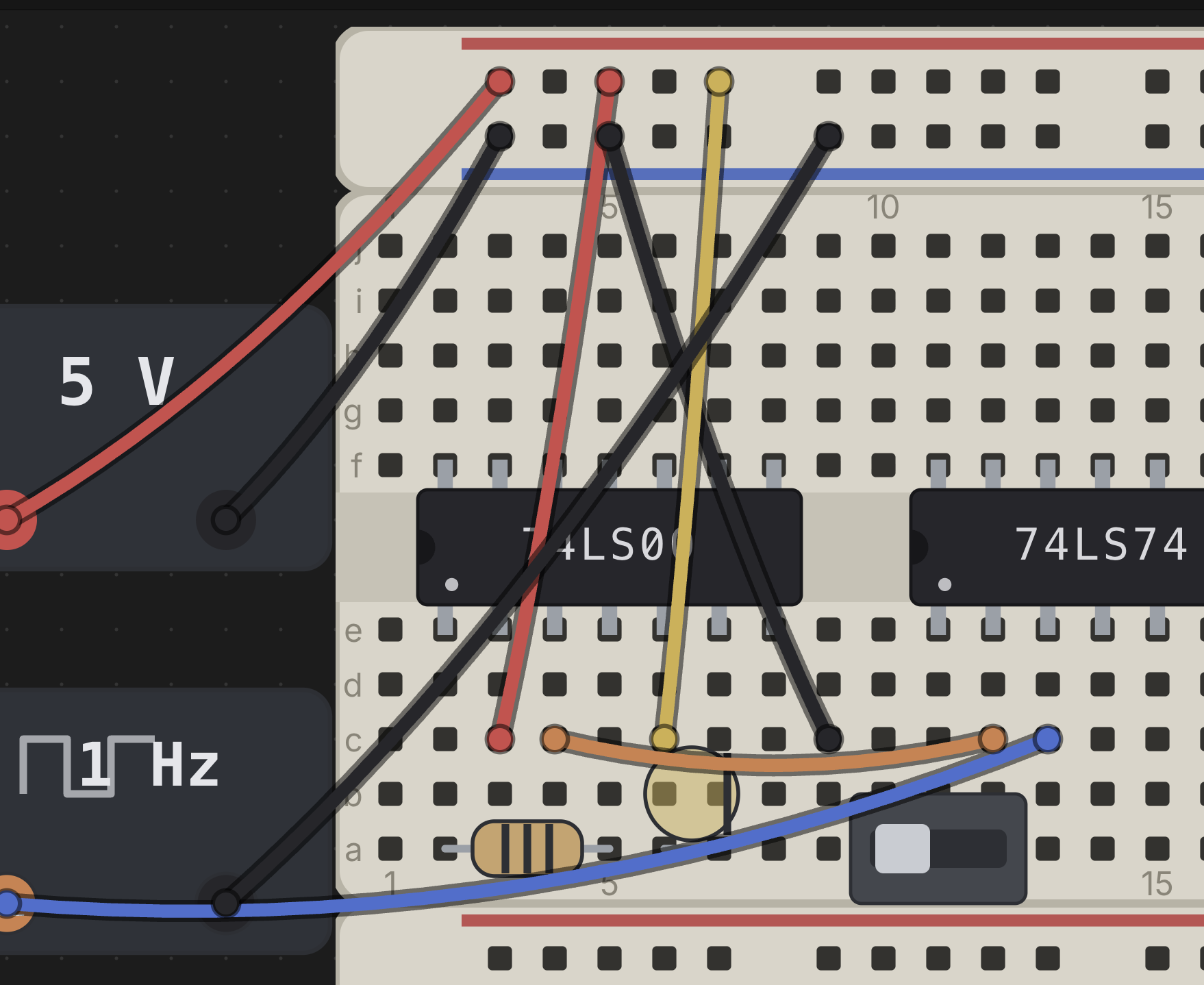
The wire tool
Press W (or click Wire in the toolbar) to arm the wire tool. With the
tool armed:
- Click a free hole or terminal to anchor the first end — a rubber-band preview then tracks your cursor.
- Click a second free point to drop the wire between them.
The tool stays armed after a wire is committed, so you can lay a whole chain of wires without re-arming — each new wire starts fresh, so it does not automatically continue from the last endpoint; just click a new starting hole. A hover ring shows the point under your cursor and turns red the moment it's over an illegal target (already occupied, or the same point you started from) — the rubber band tints red too, so a bad landing is obvious before you click.
Press Esc to cancel a pending (anchored-but-not-yet-dropped) wire without
leaving the tool, or Esc/click Wire again to disarm it entirely. M
also disarms whichever of the wire, bus, or probe tools is currently
armed — one key to "put the tools away." The wire tool (like the bus and
placement tools) is unavailable while a simulation is running; editing is
locked until you press Stop.
Wire colors
Chip Hippo ships eight wire colors: red, black, blue, green, yellow,
orange, white, and purple. The active color is shown as a swatch dot on
the toolbar's Wire button — click the dot itself to open the palette and
pick a different one (picking a color sets it without arming the tool, so
you can set up a color before you start wiring). Clicking the word Wire
beside it still arms the tool as usual. While the tool is armed you can also
press a digit 1–8 to jump straight to a color (1 = red, 2 = black, and so
on through the list above). The color you pick stays pinned between
wires — laying a chain of jumpers keeps whatever color you last chose, so pick
red for a supply run and black for ground and they'll stay that way until you
deliberately switch.
You can also recolor a wire after the fact: right-click it and choose Properties…, which offers the same eight swatches alongside the wire's name, description, layout method, and the drawing of the wire itself described below. (Delete Component on that menu is how a wire is removed.)
Wire length
The last thing in a wire's Properties… dialog isn't a field at all — it's a picture of the wire, drawn across the card in its own colour with the sleeve stripped back at both ends to bare tinned lead, and a dimensioned line underneath giving its length in centimetres.
It answers the one question the desk can't. On the desk a wire is a curve between two holes at whatever zoom you're at, so its length is unreadable — and its length is exactly what you need before cutting one off a spool.
Two things about that figure:
- It's the cut length, not the run. A real jumper doesn't stop at the surface of the board — it has to reach into both holes — so a wire crossing a single 0.1 in pitch is about 13 mm of wire, not 3. The sleeve in the drawing spans the run; the bare tips are the two stripped ends; the dimension spans the lot.
- The length follows the drawn shape, not the straight-line distance: the sagging curve's own arc for a direct wire, the polyline through the waypoints for a routed one, and for a bus member its lead plus the whole ribbon plus its far lead — a conductor inside a ribbon cable is as long as the cable, however short the ends sticking out of it are.
It's the same measurement, and the same wording, as the Wires cutting list in the build guide — so a wire can't read one length here and another there. Recolor the wire in this same dialog and the drawing repaints to match.
Cross-board wires
A wire's endpoints don't care which board or brick they land on — you can run a wire from one breadboard to another, from a board to a PSU terminal, or between two separate strips, exactly as freely as within one board. When you drag a board that a wire is attached to, the wire's other end stays put and the whole wire stretches and re-sags live, riding the move; nothing needs to be re-laid. Deleting a board cascades: any wire with an end seated on that board is removed along with it.
Moving a part works the same way from the wire's point of view: the wire ends plugged into its pins' column-halves come along, and each wire's other end stays put and stretches — for one part, or for a whole selection of them. See Chips & Components for the rules.
Re-routing & deleting a wire
Grab a wire two different ways:
- The wire itself — press anywhere on it, its end caps included, and drag to translate the whole wire rigidly, keeping its length and orientation and just sliding both ends together onto a new pair of holes. If either landing point isn't free, the wire snaps back on release. (A plain click on it just selects it.)
- One end, with
Option(Alton Windows and Linux) — hold it and the wire's end holes ring red as you hover them; drag one to a new hole or terminal to re-route that end while the other stays put. The end follows the cursor and snaps onto a free hole once it's within about a hole's reach of one. A hover ring and red/legal tint on the dragged end work exactly like placing a fresh wire. Letting go drops the end on the hole the ring was showing; with no ring, or a red one, the end snaps back to where it started. See Selecting things.
To delete a wire, click it to select it, then press Delete or Backspace
(the same shortcut removes whatever's currently selected — a part, a board,
or a wire).
Wire layout: direct or routed
Every wire is drawn one of two ways, its Layout Method — right-click a wire and choose Properties… to switch it:
- Direct (the default) — the wire sags gently from one hole to the other, the way a real jumper lead does. There is nothing to position: the shape follows the two ends.
- Routed — the wire runs as straight lines, and you decide where it goes. This is the one to reach for when a run would otherwise cross the middle of a chip, or when a tidy right-angled layout reads better than a fan of curves.
A routed wire starts as a single straight line. Bending it is an Option
(Alt) job:
Option-drag anywhere along the wire (anywhere but its two ends). A new point is added where you grabbed it, and the wire now runs start → point → end. Repeat to take it around whatever is in the way — up to twenty points per wire. Hover the wire withOptionheld and a red ring marks where the new point will go.Option-drag an existing point to move that bend somewhere else.- Drop a point onto a neighbouring point, or onto either end of the wire, and it merges away — that's how you take a bend back out. The point you are dragging turns red as it lands, so you can see the merge before you release.
Option-drag an end onto one of the wire's own points and that point is absorbed: the wire now reaches where the bend used to be, so the bend has nothing left to do.
A plain drag — no Option — never bends a routed wire: it picks up the
whole wire, both ends and every bend, and moves it as one piece. Both ends
have to land in free holes; if they can't, the wire snaps back where it was.
Selected together with something else (a box, or Cmd/Ctrl-click), it moves
the same way with the rest of the selection.
Switching a wire back to Direct deletes every point it carried and redraws it as the plain
sagging curve; switching to Routed straightens it out, ready for points.
Either way it's one undo step (Cmd/Ctrl+Z), as is every individual bend.
Settings ▸ Appearance ▸ Wire layout picks which of the two a newly laid wire gets. It's read when the wire is laid, so changing it never disturbs wiring already on the desk. Circuits built by the AI builder always arrive direct, whatever that setting says — the builder places holes, not hand-drawn routes.
Auto-routing every wire
Auto-route wires in the toolbar tidies a whole desk in one go: every wire becomes a routed wire running straight along the board, around the parts and clear of the other wires, instead of a fan of curves crossing the chips.
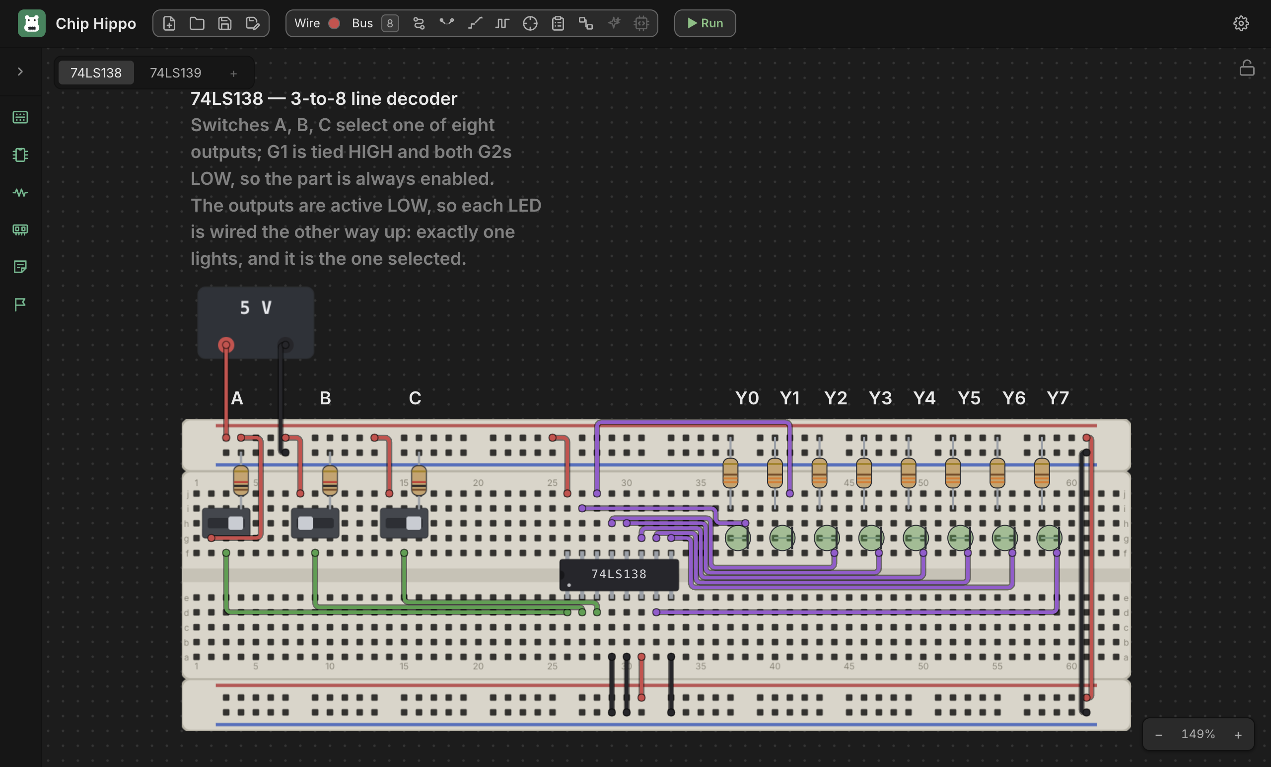
It asks first, saying how many wires it will redraw, because it replaces every bend placed by hand. To find a clear lane it may also move a lead to another hole on the same connection — along the same power rail, or within the same five-hole strip — so the circuit itself never changes. A wire it can't find a path for is left exactly as it was, and the message at the end says how many. Bus wires are left to their ribbon.
With something selected, only the selected wires are redrawn — along with
the wiring on any selected board, and a wire whose end you have picked — and
every other wire stays exactly as it is, the new runs steering around it. The
question then counts them against the whole desk (3/9 wires will be redrawn…). A selection with no wires in it routes nothing and says so: clear
the selection to route every wire, or select the ones you want.
A large desk can take a few seconds; the message says how far it has got, and
its Cancel button stops it with nothing changed. The whole result is one
undo step (Cmd/Ctrl+Z). Like any other wiring change, it does nothing while
the circuit is running.
Addresses
Wires never store pixel positions — they store addresses, the one
cross-module currency for anything wireable. An address is
<ownerId>.<point>:
bb1.a12— a grid hole (board idbb1, holea12).bb2.+7— hole 7 on a rail strip's+rail.psu1.+— the+terminal of a PSU brick.
A wire's from/to are just two of these addresses, plus a color. One
hole or terminal holds at most one lead — one pin or one wire end — so the
occupancy check that keeps the wire tool's hover ring legal/illegal is the
same one that governs seating a chip or a discrete. Because everything
resolves through addresses rather than coordinates, a wire keeps working
correctly no matter how the boards around it get rearranged.
Buses
For a wide, tidy bundle — a data or address bus — press B (or click
Bus in the toolbar) to arm the bus tool instead of laying eight wires by
hand. It's click-click like the wire tool: anchor a start hole, then click a
second point to lay the whole run in one go, rendered as a single fat band
rather than a fan of individual wires.
Before you click, set the width. The circled number on the toolbar's
Bus button shows the active one, and clicking it opens the presets in a
row: 2, 3, 4, 5, 6, 7, 8 and 16 bits, the current one ringed. Picking one sets
the width without arming the tool, so you can set up before you start. From
the keyboard — while the bus tool is armed — 2–8 lay a bus that many bits
wide (4 → D[3:0]) and 1 lays the 16-bit bus (D[15:0]); no single digit
can spell 16, and the widest bus is worth the first key. The width names the
bus too (D[3:0]); rename a placed one from its context menu.
Landing the second click on a chip pin group (a catalog-defined bus of pins, like a chip's data lines) fans the bus onto those pins in bit order, instead of marching it down a second run.
Both ends have to fit. A bus claims one hole per bit at each end, so as you move the cursor every hole it would take is ringed — in the hover color when they're all free and on the strip, in red when they're not, and a red set can't be clicked. Aim an 8-bit bus five columns from the end of a board and you'll see five red rings instead of eight, which is the whole explanation: the run doesn't fit there. That check runs on the first click as well, so a start that could never work is refused where you make it rather than looking like the far end is at fault.
A bus is metadata layered over the individual wires it lays — right-click a placed bus to Rename, Recolor (which recolors every member wire too), Un-bundle (keep the wires, drop the bus grouping), or **Delete bus
- wires**. Drag a bus by its band to move every member wire together.
See also
- Chips & Components — placing the parts a wire connects.
- Power & Clock Sources — PSU and clock brick terminals, which wires reach exactly like board holes.
- Probing & Net Names — inspecting the nets your wires and buses form, and naming them.