Power & Clock Sources
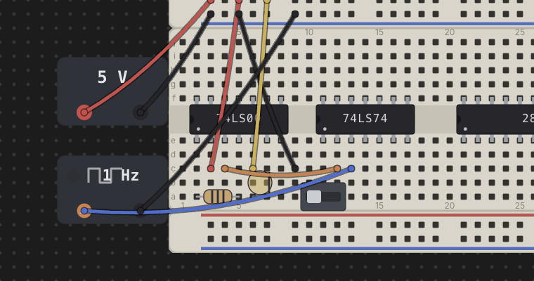
Every circuit needs somewhere to draw power from and, for sequential parts, a signal to step them along. Chip Hippo gives you two kinds of desk-level bricks for this — a power supply (PSU) and a clock source — neither of which seats on a breadboard. They sit loose on the desk with their own addressable terminals, and you wire those terminals into a board's rails (or straight to a chip's pins) just like any other wire run.
There is a third kind of source, and it does not live on the desk at all: external signals, the bench stimulus buttons pinned down the right-hand edge of the viewport. They are covered at the end of this page.
PSU bricks
Add a Power supply from the parts palette (Power group) and drop it
anywhere on the desk — it isn't tied to a board. It draws as a small body with
a voltage badge and two terminal pads: a red + and a black −.
Those pads are addressable wire endpoints, psu1.+ and psu1.- for the
first PSU you place, exactly like a breadboard hole — click-click a wire from
each terminal into a power rail (or directly to a chip's VCC/GND pins) to
energize a circuit.
A PSU has no on/off switch of its own — it's always "live" the moment the simulation is running; what matters is which voltage it's set to and what it's wired into.
Its Properties also set a Current limit (1 A unless you change it). The standard engine never reads it. Under Spice Lite the brick shows the current being drawn, and a supply asked for more than its limit droops. To load one on purpose, put an electronic load across it; to get a second voltage from it, a regulator.
For alternating current there is an AC adapter for low-voltage AC on the board, and a mains brick with a transformer to look inside a linear power supply. All three are shown only while Spice Lite is on: see AC supplies and transformers.
Choosing a voltage — and the damage rule
Right-click a PSU brick and choose Properties… to pick its voltage: 3 V, 5 V, 9 V, 12 V or 15 V. It's a live setting — the dropdown stays available and applies immediately even while the simulation is running, so you can change voltage on the fly and watch the effect.
What a voltage does to a chip depends on the chip's logic family — each chip is held to the supply its datasheet rates it for:
| Supply | 74LS (TTL) and the memory, interface and processor chips | CD4000 (CMOS) |
|---|---|---|
| 3 V | underpowered — inert | runs |
| 5 V | runs | runs |
| 9 V, 12 V, 15 V | damaged — magic smoke | runs |
- Runs — a chip whose VCC net carries a supply inside its range and whose GND net is properly grounded behaves exactly to its datasheet.
- Underpowered — the chip is inert (every output floats, as if disconnected) but nothing is harmed. A 74LS part needs 5 V; at 3 V it does nothing.
- Damaged — this is Chip Hippo's "magic smoke" rule: any chip (or oscillator can, which is powered the same way) whose VCC net sees more than its range allows is immediately marked damaged and goes inert for the rest of that run, independent of anything else on the net. A 74LS part is rated for 5 V, so 9 V, 12 V and 15 V all destroy it; a CD4000 part runs anywhere from 3 V to 18 V. It stays dead while the run lasts — a failed chip doesn't recover while the power is still wrong — and Stop makes it whole again.
So one board can run a CD4000 chip happily at 12 V while the 74LS chip beside it smokes — which is exactly why, on a real bench, people ran 4000-series chips at 5 V whenever the two families had to share a supply. The warning says the voltage the chip saw and the supply it is rated for.
A chip can also come up reversed — a PSU − on its VCC pin's net at the
same time as a PSU + on its GND pin's net — which is reported separately
from plain unpowered/underpowered, since it specifically means the supply
leads are swapped.
Live chip health (powered / underpowered / reversed / damaged) shows as a badge on each chip while running — see Running a Simulation for how those badges and the rest of the settle model work. This page only covers what puts a chip into each state.
Two supplies on one desk
You can place as many PSUs as you like. Give each one its own + rail — a separate rail strip, or one half of a Split power rail — and the chips on each rail run at that supply's voltage. The grounds can be wired together, and usually should be.
What you can't do is join two supplies set to different voltages on the same + net, for example by jumpering the two + halves of a split rail. On a real bench the higher supply pushes current back into the lower one. Chip Hippo reports it as Supplies meet — a warning when you run, and a fault in the desk review — naming the voltages involved, and runs the net at the higher one until you fix the wiring. Two supplies at the same voltage on one net aren't reported.
Recovering from an over-voltage mistake
Press Stop. Every damaged chip on the desk is restored, and you can rewire and run again. You don't lose the part, and you don't have to delete and re-place anything.
Over-voltage is meant to be noticed, not to cost you the chip: the red badge and the warning are the point, and they've done their job by the time you stop. Wiring a supply to the wrong rail is a mistake about the circuit — one you can see and fix — so it stays fixable. Find where the high supply is reaching a 74LS chip's VCC net (the probe tool is the quick way), correct it, and press Run.
Clock sources
Add a Clock source from the palette (Power group) for a free-running
or manually stepped square wave to drive a sequential chip's clock pin. Like
a PSU, a clock brick is desk-level — it doesn't seat on a board — and exposes
three addressable terminals: out, vcc and gnd (clk1.out,
clk1.vcc, clk1.gnd). Wire out to a chip's clock input.
A clock is an instrument, and like every instrument on a bench it needs
power: wire vcc to the + rail and gnd to the − rail. Its HIGH is then
that supply's voltage, so a clock on a 5 V rail clocks a 5 V circuit. A clock
with no power does not tick — its output drives nothing and its lamp stays
dark — and if its out is wired into the circuit, running warns Clock not
powered until you wire it up.
Right-click a clock brick and choose Properties… to set its rate:
1 / 2 / 5 / 10 / 20 / 50 / 100 / 250 / 500 Hz, 1 kHz — free-running. Once the simulation is running, the brick toggles its
outlevel on its own at the chosen rate; a small lamp on the body lights while the output is HIGH. The slow end is for watching a single edge land; the fast end is for letting a counter or a CPU actually get somewhere while you watch. Above about 20 Hz the lamp and any LEDs on the circuit blur together — that's the point at which the logic analyzer becomes the way to see what happened. An LED, or a display segment, that switches on and off faster than the desk is redrawn is drawn at its average over each frame, as your eye sees a real one: lit a fifth of the time, it glows a fifth as bright. Once anything on the desk toggles faster than 25 Hz (the fastest clock or timer, times the speed), every lamp drops its glow halo and shows just its colour: a glow that fast is only a flicker, and drawing it costs more than anything else on the desk.While the simulation runs, a free-running clock also shows a small ⏸ button in its top-right corner. Click it to hold that one clock: it keeps whatever level it was at — its lamp and everything it drives stay as they were — while the rest of the circuit, and every other clock, carries on. The button turns into a ▶; click it again to set the clock going. A clock's own pause belongs to the run, like its phase: Run always starts every clock going, Step passes a paused clock by, and resuming the transport after Pause leaves it held.
Custom… — any other rate, from 1 Hz to 10 kHz. Picking it opens a Custom rate box under the list, filled with the clock's present rate; type the rate and press Enter (or leave the box). Plain hertz, a
kfor kilohertz, and the unit are all fine:1500,1.5k,1.5 kHzand1500 Hzare the same rate. A rate that doesn't read, or lies outside the range, turns the box red and says why, and the clock keeps the rate it had. The clock runs exactly as a listed rate does — Pause, Step and the speed button included. Past 2 kHz an amber (i) appears beside the box: a desk may not be able to keep up with an edge that often, and the simulation then slows itself as necessary (the speed button shows the speed it is actually managing — see Simulation).Manual — click-to-toggle. No timer runs it; instead, while the simulation is running, clicking the brick's body flips
outfrom LOW to HIGH (or back) once per click — handy for single-stepping a counter or flip-flop by hand and watching each edge land.
The rate, like the PSU's voltage, is a live setting — it applies immediately and stays available while running, so you can retune a clock's speed mid-simulation.
The card's Wave type is Square (the default) or PWM. A PWM clock is a square whose HIGH lasts its Pulse width — a slider from 1 % to 99 % of each period, 50 % (the square) unless you move it — and LOW for the rest: a 10 Hz clock at 25 % comes up 75 ms into each period and goes down 25 ms later. The pulse width, like the rate, applies while running; moving it keeps the clock's place in the half it is in, so dragging the slider never holds an edge off. Step moves a PWM clock by the half it is in, and the glyph on the brick is drawn at its pulse width. An LED driven by a fast PWM clock looks as bright as its pulse width: at 250 Hz and 20 %, a fifth as bright as one lit steadily — dimming an LED, as on a bench. The slider is greyed for any other wave, and for a manual clock.
With Spice Lite on, the Wave type also offers Triangle, Trapezoid — the square with sloped edges — Sawtooth (ramp up) — it climbs and drops straight back — Sawtooth (ramp down) — it drops and climbs straight back — or Sine. Each swings from 0 V to the clock's supply once per period of its rate, starting at its low point (a ramp down starts at the top), and the glyph on the brick shows which. Set its Amplitude (peak to peak) and Offset (the voltage it is centred on) to swing it anywhere else — 1 V about 2.5 V, say; left blank they are the whole supply about half of it. A swing that would pass 0 V or the supply is clipped flat there, as a generator powered from those rails would be. The standard engine has no voltages, so with Spice Lite off such a clock is the square its levels are, and the brick draws one, whatever the card is set to. A manual clock is always square.
An oscillator can (a discrete part that seats directly on a board rather than as a desk brick) behaves the same electrically — it's a free-running square-wave source powered like a chip, with its own rate field in its Properties dialog — but it only ever free-runs; a real crystal has no click-to-toggle pin, so it has no manual mode.
The transport drives the edges
Free-running clocks (and oscillator cans) don't tick on their own outside a
simulation — their edges are driven by the Run/Pause/Step/speed transport
in the header, described fully in
Running a Simulation. Briefly: Run (Space) starts
every free-running clock at its configured rate; Pause freezes them in
place without stopping the simulation; Step advances every free-running
clock by exactly one half-period and re-settles the circuit, useful for
watching a sequential chain edge by edge; and the speed control scales
every free-running clock's rate together (it has no effect on a manual
clock, which only ever moves on a click). A manual clock only responds to
clicks while the simulation is actually running — stopped, its body is inert
like everything else on the desk.
External signals
A signal is bench stimulus: a labelled button pinned to the right-hand edge of the desk, and a pointed flag whose tip plugs into any hole on any breadboard. Pressing the button injects a level at that hole. Nothing about a signal takes up board space, and — unlike a push button, which you can only hold one of at a time — you can assert several signals at once.
Add one from the parts palette's SIGNALS section: pick Signal, then click anywhere on the desk. The click position does not matter; the button always goes to the next free slot on the rail, with its flag waiting beside it.
Each button's coloured dot shows the key that presses it — 1 for the top
button, down to 9, then 0 for the tenth — and the flag prints the same key
inside its body. That key is how you tell a flag's button at a glance.
Selecting a flag on the desk also outlines its button on the rail.
Drag the flag onto a board and its point snaps into the hole under the cursor. Press R while it is selected to turn it a quarter-turn about that point, so it can lie in whichever direction has room. A flag claims its hole exactly like a wire end or a chip pin does, so nothing else can use it while the flag is there.
To take a flag off the board, drag it onto bare desk, or right-click it and choose Remove Signal. Either way the flag goes back beside its button on the rail, and its position and rotation are cleared, so the next drag starts fresh. The signal itself stays. Delete Signal on the same menu (or the Delete key while the flag is selected) removes the signal altogether, button included.
Momentary, toggle, and the resting level
Right-click a flag (or a button) for Properties…:
| Field | What it does |
|---|---|
| Name | The label shown on the button |
| Description | The button's tooltip |
| Color | The colour shared by the button's dot and its flag — any of the seven signal colours, even one another signal already uses |
| Type | Momentary asserts while held; Toggle flips on each press and stays |
| Default value | The level the signal rests at — Low or High |
A placed signal is always driving its net. A momentary signal rests at its
default and asserts the opposite while you hold it, which is what makes
"Default: High" the natural setting for an active-low /RESET line: it sits
high, and pressing the button pulses it low. A toggle's current level is reset
to the default every time you Run, so a run always starts from a known state.
A signal drives at the same strength as a chip output, so two signals arguing over one net — or a signal fighting a chip's output pin — is reported as a conflict, exactly as two chip outputs on one net would be.
Pressing them
While the circuit is running, 1–9 and then 0 press the signal buttons, top
to bottom — the key each button (and its flag) shows. No modifier, so you can
hold several down together — 1 and 3 at once is two signals asserted at
once. (Those digits pick the wire colour and the bus width
while the Wire or Bus tool is armed, but Run puts both tools away, so the two
meanings never collide.) Clicking a button with the mouse does the same thing
for one signal at a time.
There are ten signals per desktop — one per digit key. The palette's Signal row goes grey once all ten are in use.
A new signal takes the next colour in the sequence red, blue, green, yellow, orange, white, purple, starting with the first one no signal is using. Once all seven are in use the sequence starts again from red, so the eighth, ninth and tenth signals share a colour with the first three — their keys tell them apart. Deleting a signal frees its colour for the next one you add. The signal colours are the eight jumper colours minus black, which is the bench's ground colour: a black flag would read as a ground tie, and its button's dot would all but vanish against the dark rail.
A project saved before black was withdrawn still opens; any signal that was black is given a colour on load, and keeps its name, type, resting level and wherever its flag was planted. Nothing else on the rail is recoloured.
Data buses — eight lines at once
A signal drives one hole. To put a whole byte on a bus — a CPU's data
lines, an adder's operand, a decoder's address — add a Data bus instead:
pick Data in the palette's SIGNALS section and click the desk. Its card
goes on the right-hand rail under the signal buttons, headed ⇉ Data 1, with
eight numbered flags waiting under the name — the same flags an 8-bit Output
has. Pin 1 is the leftmost and is bit 0.
Drag a flag onto a hole exactly as you would a signal's. Its place on the card becomes a box of the same size showing Z. Click the box to set what that flag drives: Z → 0 → 1 → Z. Z (high impedance) drives nothing at all, as though the flag were not there; 0 and 1 drive the hole low and high at chip-output strength, so a data line fighting a chip output is reported as a conflict, like a signal. Flags you have not placed stay on the card as numbered chips.
The levels are part of the design: they are saved with the project and are the same the next time you Run. You can click them while the circuit is stopped (each click can be undone) or while it runs — that is the point, set a byte and watch the board answer — and a level changed during a run stays after Stop, the way a slide switch thrown during a run does.
A flag taken off the board (dragged onto bare desk, Remove Tag, or a board deleted from under it) goes back to its card and back to Z, so it never arrives on the board again already driving. Moving a flag from hole to hole keeps its level. Properties… sets a Data bus's name, description and colour; Delete Data removes it, flags and all.
Each Data bus has a colour of its own — eight flags in one colour read as one byte on the board — so there are up to seven, one per signal colour, counted apart from the Arduino Outputs and Inputs. A new one takes a colour no other Data bus has (one no signal is using, while there is one), and its Properties… offer only the colours still free. They have no keys — they are set from the card. A Data bus talks to no Arduino and never stops a Run.
A Data bus's 0 is 0 V on the bench's own ground, as a signal's LOW is. On a board whose − rail is not that ground — one fed by a bridge rectifier straight off Mains, with no transformer, swings far below it every cycle under Spice Lite — a 0 still pushes current through whatever joins the flag to that rail, so an LED there can light on a 0.
See Wiring, Nets & Buses for how to route power-rail and clock wiring generally, and Running a Simulation for how power state and clock edges feed into the settle model and live views.